
*This post contains affiliate links, so we may earn a small commission when you purchase through links on our site at no additional cost to you.
It is important when wiring your solar panels that it is done correctly to unlock their full potential. How you wire your solar panels depends on your situation such as whether you have full sun with no space constraints or shaded areas with space constraints. In this guide, we'll walk you through the ins and outs of wiring solar panels in both series, parallel, and hybrid configurations, provide easy-to-understand formulas, discuss wire gauges, and some of the things to look out for when choosing solar panels. You ready?
Wiring Basics: Series vs. Parallel
Before diving into the technicalities, let's understand the basic difference between wiring solar panels in series and parallel.
Series Wiring: Connect the positive terminal of one solar panel to the negative terminal of the next. This adds up the voltage while keeping the current (amperage) constant.
Pros:
- Increased voltage means an increase in power output,
- low amperage requires less hefty cables/components,
- great for shade
Cons:
- If one panel is shaded or obstructed from direct sunlight, creates poor performance for all panels.
Parallel Wiring: Link the positive terminals together and the negative terminals together. This increases the current (amperage) while maintaining a constant voltage.
Pros:
- Performance isn't dependent on the other panels,
- Best for small, low-voltage systems,
- Performs well in occasional shade or mixed-light environments
Cons:
- Requires thicker cables to handle the higher amperage
As you can see, the two main numbers to pay attention to when choosing and wiring solar panels are voltage and amperage. Both wiring systems have unique pros and cons. You can achieve the best of both worlds by using a combination of the two, more on that later in this article.
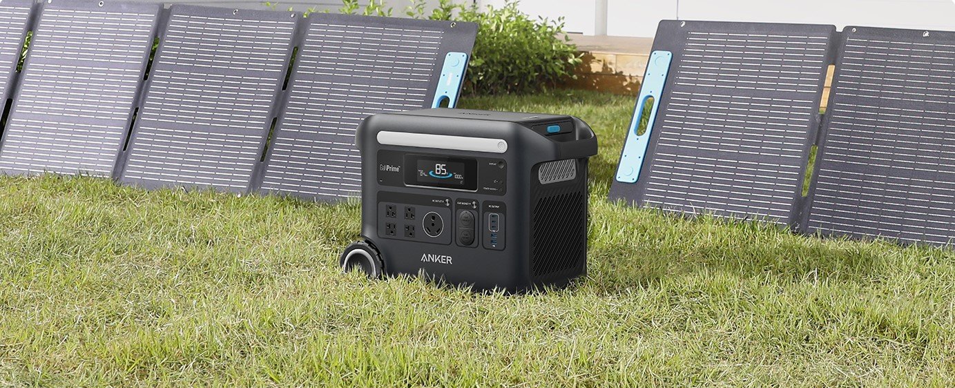
Pictured: Anker SOLIX F2600 with 2x 200W Solar Panels
How Does Wiring Solar Panels in a Series or Parallel Affect Voltage and Amperage?
Wiring in Series:
When you wire solar panels in series, you connect the positive terminal of one panel to the negative terminal of the next panel, and so on. This increases the total voltage of the system while keeping the current (amperage) constant.
- Voltage: In a series circuit, the voltage across each component adds up. So, if you have two solar panels with a voltage of 12 volts each and you wire them in series, the total voltage would be 24 volts (12V + 12V).
- Amperage (current): In a series circuit, the current remains constant. Therefore, the total amperage of the circuit when solar panels are wired in series remains the same as the amperage of an individual panel.
Wiring solar panels in series affects the voltage and amperage, but not the total wattage. When solar panels are wired in series, the voltage of each panel is added together, while the amperage remains constant. The total wattage output is the product of the total voltage and total amperage.
Here's an easy-to-understand formula:
- Voltage: V_total = V1 + V2 + V3 + ...
- V_total is the total voltage when solar panels are wired in series.
- V1, V2, V3, ... are the voltages of individual solar panels.
- Amperage: A_total = A1 = A2 = A3 = ...
- A_total is the total amperage when solar panels are wired in series.
- A1, A2, A3, ... are the amperages of individual solar panels.
A real-world example of wiring in series:
Let's say you have three solar panels with the following specifications:
Panel 1: 12 volts, 5 amps
Panel 2: 12 volts, 5 amps
Panel 3: 12 volts, 5 amps
If you wire these panels in series:
- Total Voltage: V_total = 12V + 12V + 12V = 36V
- Total Amperage: A_total = 5A (since amperage remains constant in series)
So, when wired in series, these three solar panels will produce a total output of 36 volts at 5 amps.
It's important to note that while wiring solar panels in series increases voltage and total wattage, it also introduces some considerations. If one panel in a series is shaded or not performing optimally, it can impact the overall output of the entire series-connected panels. Additionally, the voltage of the series-connected panels should not exceed the input limits of the charge controller or power station used in the solar power system. If the voltage is too high, it may damage the electronics.
Wiring in Parallel:
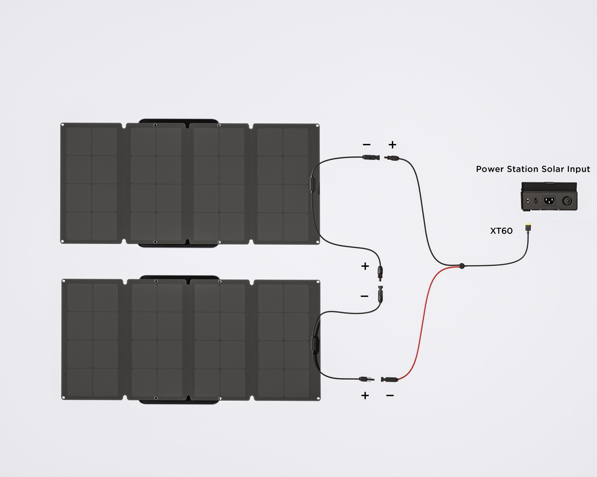
When you connect solar panels in parallel, the positive terminals of all panels are connected, and the negative terminals are connected. This results in a single output connection for both positive and negative terminals. Here's how wiring solar panels in parallel affects amperage, voltage, and wattage:
- Voltage: Voltage remains the same in parallel connections. If you have, for example, two solar panels with a voltage output of 18 volts each and you connect them in parallel, the total voltage at the output will still be 18 volts. Parallel connection does not increase the voltage; it maintains the voltage of an individual panel.
- Amperage (current): Amperage increases in a parallel connection. If you have two solar panels with a current output of 5 amps each and you connect them in parallel, the total current at the output will be the sum of the individual currents. In this example, the total current will be 10 amps. Connecting panels in parallel increases the total current capacity.
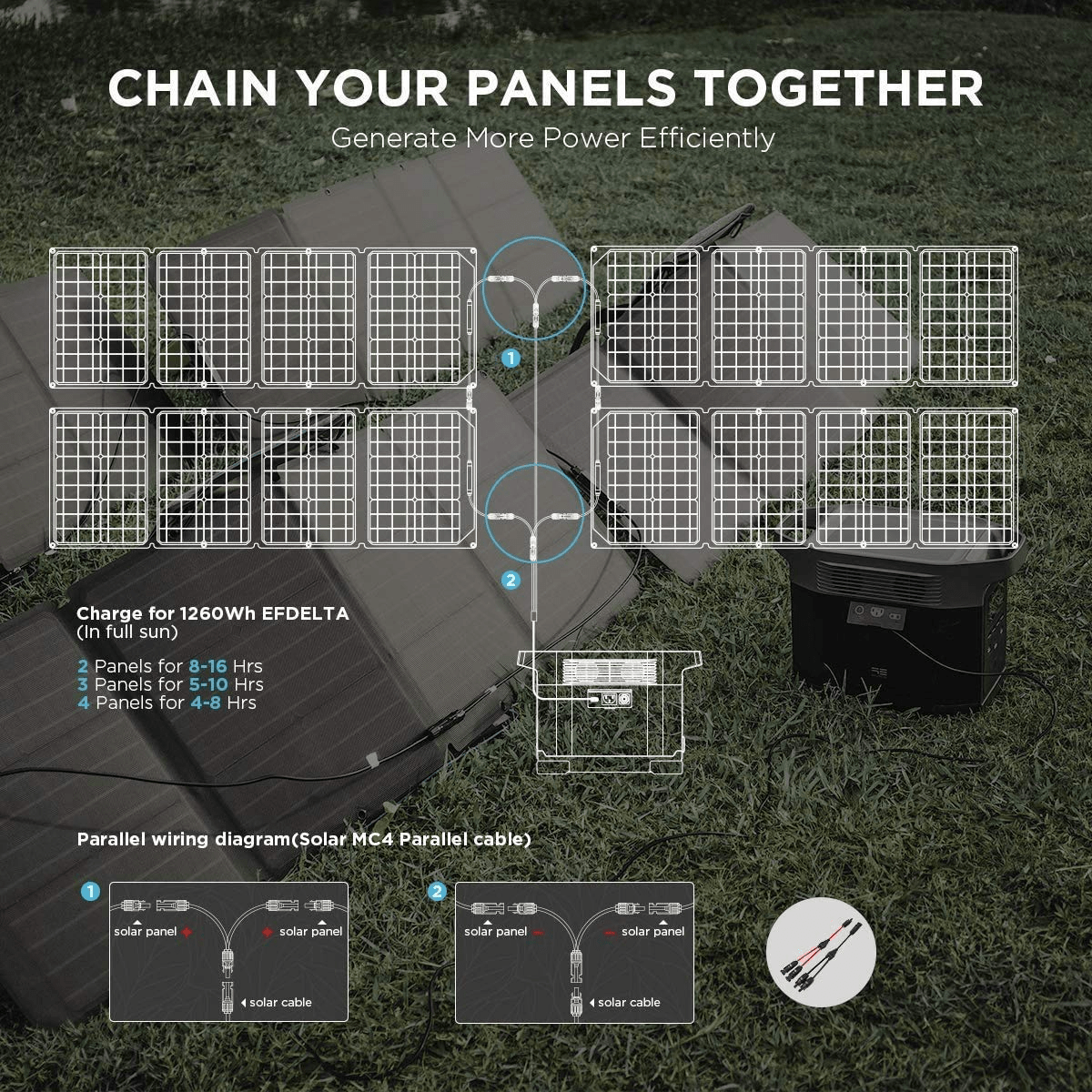
Pictured: EcoFlow Delta 1300 with 4x 110W Portable Solar Panels and Solar MC4 Parallel cables
The formulas to understand wiring in parallel:
-
- Voltage: V_total = V1 = V2 = V3 = ...
- V_total is the total voltage when solar panels are wired in parallel.
- V1, V2, V3, ... are the voltages of individual solar panels.
- Amperage: A_total = A1 + A2 + A3 +...
- A_total is the total amperage when solar panels are wired in parallel.
- A1, A2, A3, ... are the amperages of individual solar panels.
Real-world example with wiring 3 solar panels in parallel:
Let's say you have three solar panels with the following specifications:
Panel 1: 12 volts, 5 amps
Panel 2: 12 volts, 5 amps
Panel 3: 12 volts, 5 amps
If you wire these panels in series:
- Total Voltage: V_total = 12V (since voltage remains constant in parallel)
- Total Amperage: A_total = 5A + 5A + 5A = 15 amps
So, in this example, the parallel connection of three solar panels results in a system with 12 volts and 15 amps.
Wiring solar panels in parallel maintains the voltage while increasing the current and, consequently, the total power output. This configuration is often used to increase the current capacity of a solar power system, especially when you have space constraints or shading issues that may affect individual panels.
Hybrid Wiring:
It is entirely possible to use a combination of both wiring setups. This will give you the benefit of both series and parallel wiring.
To maximize your solar array using this method:
- Wire panels together in strings using the series wiring method. Such as 2 sets of 4x 100W solar panels, with 8x 100W solar panels in total.
- Then, use the parallel wiring method to connect those two strings.
When connecting strings of series-wired panels using parallel wiring, you add the amperage values of each string together. This way you get both higher outputs of voltage and amperage.
Wire Gauge Matters: 10 AWG vs. 12 AWG
The difference between 10 AWG (American Wire Gauge) and 12 AWG solar extension cables lies in their wire thickness or gauge, and this affects their electrical conductivity and current-carrying capacity. AWG is a standardized system used to measure the diameter of electrical wires, with a lower gauge indicating a thicker wire. MC4-to-MC4 and MC4-to-XT60 extension cables are often 10 AWG and 12 AWG but also come in 8 AWG. Which gauge you choose will depend on the following factors:
- Wire Thickness:
- 10 AWG: It has a larger diameter compared to 12 AWG, making it a thicker wire.
- 12 AWG: It has a smaller diameter compared to 10 AWG, making it a thinner wire.
- Current-Carrying Capacity:
- 10 AWG: Being thicker, it has a higher current-carrying capacity than 12 AWG. This means it can handle more electrical current without experiencing significant voltage drops.
- 12 AWG: It has a lower current-carrying capacity compared to 10 AWG. While suitable for many applications, it might experience more voltage drop over longer distances or when carrying higher currents.
- Resistance:
- 10 AWG: With its thicker cross-sectional area, it has lower electrical resistance compared to 12 AWG. Lower resistance results in less voltage drop and more efficient power transmission.
- 12 AWG: It has higher resistance compared to 10 AWG, leading to slightly more voltage drop under similar conditions.
- Application:
- 10 AWG: Typically used in situations where higher current-carrying capacity is required, such as longer cable runs or higher-power solar installations.
- 12 AWG: Suitable for applications with lower current requirements or shorter cable runs.
When selecting between 8AWG, 10 AWG, or 12 AWG solar extension cables, consider factors such as the distance the cable needs to cover, the amount of current the system will handle, and the specific solar installation requirements. Always follow the manufacturer's recommendations and local electrical codes to ensure a safe and efficient solar power system.
Protecting Power Stations and Batteries
Now, let's avoid any sparks flying or magic black smoke puffing out of places where they shouldn't.
- Overloading: Ensure your wiring can handle the combined current of all panels. Don't overload the wires, connectors, or the charge controller. It is important to check the manual of your power station or charge controller. The specifications will give you the total open circuit voltage (VoC), amperage, and wattage the device can handle.
- Voltage Drop: Longer wire runs can result in a voltage drop. Choose the right wire gauge to minimize this effect and maintain system efficiency. Another factor that affects voltage is temperature.
- Check Polarity: Ensure proper polarity when connecting panels. Reverse polarity can damage your equipment.
- Use Proper Connectors: MC4 connectors are popular for their reliability. XT60 and XT60i cables provide a secure connection for low-voltage systems. Ensure they are compatible with your setup.
- Use Quality Components: Not all wires and connectors are manufactured with the highest quality. Buying ones that are of quality can be more expensive but well worth it in the long run. The last thing you want is to fry some wires, start a fire, or damage your equipment.
Wiring your solar panels need not be a daunting task. With the right knowledge, you can set up a robust and efficient solar power system. Choosing to wire in series or parallel is based on your situation. Do you have space to wire your panels in a series with ample amounts of sun? Or, do you have space constraints and shading throughout the day? Should you wire them with a combination of both based on your circumstances? It is common for people to use hybrid wiring for rigid solar panels depending on the power station's open circuit voltage max, again that is the number you do not want to exceed. Whichever way, with the knowledge you now have, you can set up your solar panels to achieve optimal performance in your situation. So, grab those MC4 connectors and XT60 cables, follow the formulas, choose the right wire gauge, and let the sunshine power up your world!


